Saturday, 4 February 2012

First Midi Test

Had another fart about tonight

1. Added a Clamping input to Multiplexer (copy of megadrum's analogue input) to use a Cymbal #2 . Works fine...in fact I might do the remaining ones like this. Grounded the rest of the unused inputs.

2. Chopped up my USB midi cable and soldered to board. Will eventually solder to the existing USB socket on the ION board

3. Connected up 9 mini jack sockets (without pots; I have only got one! )

Beer is optional


Also connected up the navigation buttons.

Connected up and it works fine, except I am getting some ghost notes here and there. I dont think it is from the Edrum as there is no channel activity (probably noise on the usb-midi )

To get over it, I tried filtering through the excellent ETRIGGER by aquawicket which worked really well to only send the  wanted notes. 


Next. Add some pots (maybe) and get it in an enclosure (maybe)

..or just stick it on the floor and play. Need to make a kick trigger though


Sunday, 29 January 2012

Multiplexer Added for 15CH Possibilities :)

I am determined to use the latest 16CH firmware so I have added the Multiplexer.

1. Removed the SIL pack and links from the Pearl Board and wired in the 3 digital inputs from the multiplexer
2. Cut the input 7 trace after the 100ohm input resistor and drilled a termination hole either side. (one side goes to input 3 of the 4051 and the other to analogue input 7 on the multiplexer
3. Put a Multiplexer on a little pcb together with the bits and bobs required for the 15ch circuit. Wired to the Pearl PCB.

It works!


Tested the switch inputs too. All that seems fine. Some more pics...


This is how it may look 
100_3196


Saturday, 28 January 2012

1 Input and Pot connected. Its coming to life...

It lives!

Looks like I will have to add the multiplexer as I get 8 inputs from Input 7 as I have it connected where the multiplexer should go..I kind of expected that.

Anywhoo, I have plugged into a couple of channels and I have no crosstalk and lots of adjustability from the pot so I am a happy bunny :)


Next is to get on with the buttons and make an input panel. (And I am short of 2 100nf caps which is an arse )

Thursday, 26 January 2012

Back to the drawing board

Well the circuit seems to be working thusfar, but the Stripboard is starting to look pretty cack so I have decided to go back a step and try to make a PCB again.

So....printing onto the board with The Toner method failed for me.

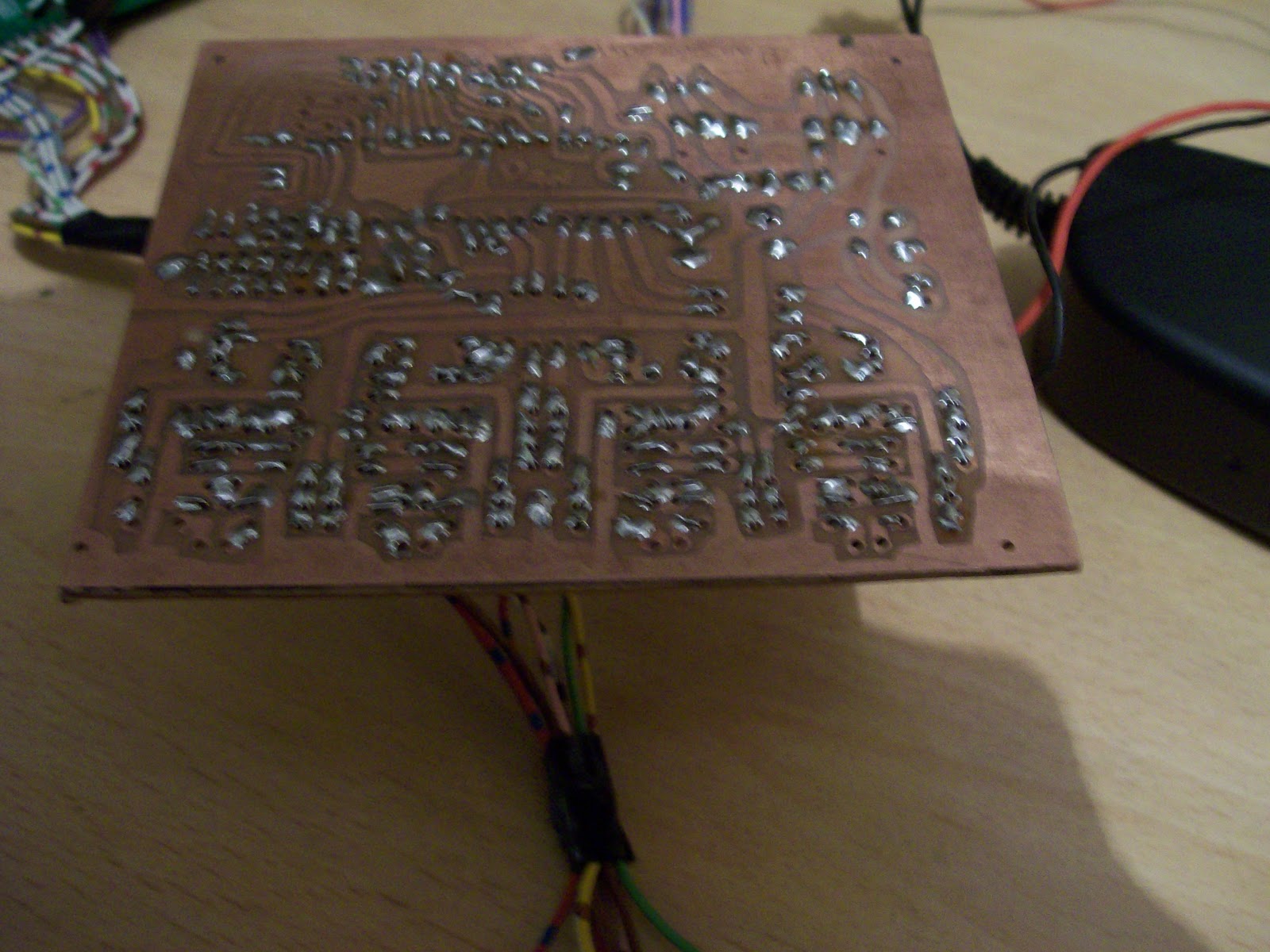
What I have done here is reversed the Pearl 8.6 PCB layout and glued it to the Copper side of the board.
I spotted the holes thorough and joined the dots with a sharpie afterwards. Forgive the crap drilling ...:)


Ill etch it in a bit and see if there is any milage in this method...

Monday, 23 January 2012

PIC programmed and Powered Up

Was rather surprised to find my pic programmer, all the way from Canada, on my doorstep .

It was only 3 quid, but arrived super quick and it worked . Its this one http://www.ebay.co.uk/itm/290617534929?ssPageName=STRK:MEWNX:IT&_trksid=p3984.m1497.l2649#ht_1202wt_905

Just plugged into the back of an old laptop, read up for 5 minutes on how to do it and the pic was programmed!


Next was a simple case of finishing most of the digital circuit and the comms with the LCD. I have tucked it all in the corner of my stripboard so, hopefully, I will have enough room left for the Analogue Circuit.

I have left the activity LED on the board for now. It might stay there. 


To be continued


None of the inputs are grounded so there is loads of activity on all channels by waving my hand around. If I grab the Heatsink of the 7805, I have to bring my finger much closer to the pins like in the Tut by raj on the Edrum forum


Sunday, 22 January 2012

LCD Backlight, contrast and Power done


Was going to run the LED on 12V and determine the correct resistors to get the correct current
(in this device it is 80ma ) as my 7805 was only rated at 100ma

In the end I replaced the 7805 for a 1A version. The LCD already has the correct resistor fitted on board to connect to 5V. Found a 22Turn Trimmer for the contrast and that worked fine too.

Onwards and upwards...need to program the PIC soon if I can beg/borrow/make/buy  a programmer


Saturday, 21 January 2012

A couple pf PCB printing fails..Stripboard it is then

So I tried a few glossy magazines and photo paper I had lying around but couldn't transfer the layout onto the copper successfully... I am sure it is just a case of finding the right paper but, well, cant be arsed really.


OK so stripboard it is. Not a bad idea as you have to have a proper read of the schematics which helps with trying to understand it all. I have decided, too, to dump the Pearl layout in favour of the 16CH dig board. Illl stick the multiplexer on the board but link for 8 CH operation so I can expand later on. 

I have made a Start here with the Power supply section. The 5/8 v tests ok and I am ready to continue. (hope my 100ma regulators are man enough ) Need to stick the extra 2 tants to the agnd rail but will sort that later on


Next: PIC and LCD  . Must also remove the jack sockets from the old board and stick on this one. I am hoping that the hole  pitch is the same as the original ION board so it fits back in to the enclosure nicely!